Part 9. Frequently Used Calculations
9.1 Intensification Ratio
The intensification ratio is a factor which is used to convert the hydraulic pressure being applied to the hydraulic injection cylinders into the actual pressure being applied to the polymer melt at the front of the screw. Since all-electric molding machines provide the actual plastic pressure, this ratio only relates to hydraulic injection molding machines.

If your injection molding machine provides the actual pressure applied to the plastic, then you should not need the intensification ratio. The following three sections explain the three most common methods of calculating the intensification ratio for your injection molding machine.
9.1.1 Machine Pressure Graph Method
Many injection molding machines provide a hydraulic pressure vs. plastic pressure graph. This graph allows the molder to take a hydraulic measurement from the machine’s pressure gauge, locate it on the graph on the horizontal axis, follow the value to the graph line and then over to the left to determine its corresponding plastic pressure on the vertical Y axis.
To calculate the intensification ratio, use the graph to locate any hydraulic pressure and its corresponding plastic pressure and then divide the plastic pressure value by the hydraulic pressure.
If there are multiple lines on your pressure graph, it is because your molding machine was offered with multiple screw diameters. To use the correct line, determine which diameter screw your machine has and locate its corresponding pressure curve.

9.1.2 Machine Specifications Method
The specifications for your molding machine can be located either in your machine manual, from other machine-related documentation, or from the manufacturer. The important information you need to obtain is the maximum hydraulic pressure and maximum injection pressure.
To calculate the intensification ratio, divide the injection pressure by the hydraulic pressure.

9.1.3 Hydraulic Cylinder Method
If you know the actual internal dimensions of your hydraulic cylinder you can calculate the exact intensification ratio of your molding machine.
To calculate the intensification ratio, multiply the number of hydraulic cylinders times the internal diameter of the hydraulic cylinder squared and then divide that result by the diameter of the screw squared.

9.2 Drying Calculations
9.2.1 Material Consumption
Before determining the dryer residence time, as well as the mini-mum and maximum dryer size, you must first determine how much material is being used. For the calculations used in this guide, we will refer to material consumption as a measure of material usage per hour. This is typically represented as kilograms or pounds per hour.
To determine the material consumption, you must know the weight of material consumed during each cycle as well as the time used to produce the product. For injection molding, the weight of the entire shot including any parts, sprue, runners, or gates produced is mea-sured. Likewise, the cycle time is provided by the molding machine.
Use the following formula to calculate the material consumption:

9.2.2 Dryer Residence Time
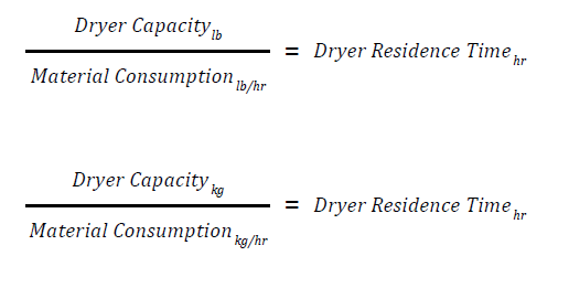
The residence time is the duration the material remains in the material dryer. Residence time is typically provided in hours. To calculate this, you will need to know the dryer capacity (in kilograms or pounds) as well as the material consumption (in kilograms or pounds per hour).
The following formula can be used to calculate the dryer residence time:
9.2.3 Dryer Capacity
The dryer capacity calculation will provide the minimum amount of material the dryer must hold to keep the material dry. Dryer size is typically provided in kilograms or pounds. To calculate this, you will need to know the recommended drying time in hours as well as the material consumption in kilograms or pounds per hour.
Use the following formula to calculate the dryer size:

9.3 Part Shrinkage
During the injection molding process, polymer is injected into the mold in the heated state. As the polymer cools, the polymer shrinks away from the mold surface. This results in a part with dimensions as much as 4% smaller than the mold dimensions. This may not sound like much, but most molded parts have very specific toler-ances which must be maintained.
Although molding technicians are rarely involved in calculating the dimensions for the mold steel, they are often asked to provide tool-makers, designers, and quality personnel with the actual shrinkage values from a similar process.
Shrinkage can be represented in one of two ways; as a ratio or as a percentage. When the amount of shrinkage that occurs is represent-ed as a ratio, the inches or millimeters cancel each other out,. As a result, a ratio of .005 in/in equals 0.005 mm/mm. This ratio means that the polymer would shrink 0.005 inch for every inch in mold cavity length. Likewise, the same ratio will imply the part will shrink 0.005 millimeter for every millimeter in mold cavity length.
Likewise, for every millimeter in mold length, the part will shrink 0.005 millimeters. To calculate the shrinkage ratio, you need to know the mold dimensions – as well as the part dimensions.
The part shrinkage equals:

9.4 Tolerances
Tolerances are typically expressed as the target value, plus or minus an acceptable tolerance. These can be placed on dimensions such as; distance, angle, diameter, or radius. In some cases, the plus dimension differs from the minus dimension.
Tolerances are typically expressed in a way which can be broken up into two different equations.
Dimension: 1.00 ± 0.01
Upper Limit: 1.00 + 0.01 = 1.01
Lower Limit: 1.00 – 0.01 = 0.99
9.5 Chiller Requirements
To determine the correct size chiller you must first determine:

9.5.1 Cooling Time
The following is the basic way to calculate the part cooling time:

9.5.2 Total Amount of Heat to be Removed
Use the following formula to calculate the total amount of heat to be removed:

9.5.3 Required Cooling Power
The following formula will help to determine the overall amount of cooling power necessary:
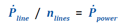
9.5.4 Cooling Power Per Line
Use the following formula to determine the amount of cooling power necessary per cooling line:

9.5.5 Required Volumetric Flow Rate
The following formula will help to determine the necessary volumetric flow rate of coolant:

9.6 Determining Screw and Barrel Wear
When determining the wear of the screw and barrel, it is important to first measure both the outer diameter (D screw) of the screw and the inner diameter (D barrel) of the barrel. Once the screw and barrel diameters have been measured, the actual clearance (C actual) can be calculated using the following calculation:

As a general rule, most molding machines are designed with a radial clearance of the 0.1% of the screw diameter (D screw). To calculate the expected clearance (C Design) use the following equation:

Once the design clearance and the actual clearance is determined,the wear (W) can be calculated using the following equation:

The acceptable amount of clearance is subject to the application, yet screw manufacturers typically suggest replacement or repair when this wear value reaches 0.05mm to 0.7mm (0.002” to 0.003”) wear for screws with a 5” diameter of less.
9.7 Barrel Residence Time
The barrel residence time is the average time the material remains within the barrel either within the flights or in front of the screw. The simplest method of determining this is to add colored pellets at the feedthroat and measure the time it takes for the molded part with the most prominent colorant to appear. The time required for the largest portion of colorant to travel through the barrel is the average residence time.
There are many complex methods of determining barrel residence time, but the method explained below is one of the easier methods:
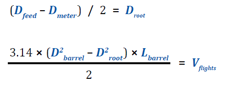
First, determine the approximate amount of material in the screw flights (V flights) using the barrel diameter ( D barrel), barrel length (L barrel) and the average root diameter ( D root) of the screw. Many molders will estimate this using the screw diameter at the feed and the screw diameter at the metering section.
Once the volume is determined, the weight (Wflights) of the material in the flights must be determined using the volume of material in the screw flights (V flights) and the material density (dmaterial).

Once the approximate weight of material in the barrel is determined, you can use the cycle time (t cycle) and the shot weight (Wshot) to estimate the barrel residence time ( tresidence).
